Dynacomp clone

A while ago I bought a MXR DynaComp clone kit, but I never got started on it. Lately I’ve been trying to tidy up my electronics-stuff and finish all my half-finished projects. So I went through the parts and realized there were a few parts that were not in the kit. I ordered the missing parts together with some other stuff that I needed and sat down to finish it.

I like to try something new for every project, some new technology or way of doing something, that I haven’t tried before. This time I wanted to etch my own circuit board. I downloaded the layout from General Guitar Gadgets and printed it on Press-n-Peel film.

SAMSUNG CSC

SAMSUNG CSC

This turned out be a very convenient way of transfering the layout once I got the printer settings right. Be sure You print the right size! There was one line that wasn’t transferred properly, but I was able to correct that with a permanent marker. Then I etched the board in ferric chloride untill all the extra copper had been dissolved.

SAMSUNG CSC

The cotton string is a good idea unless You like getting acid on your fingers.

SAMSUNG CSC

Then I did the ususal drilling (1 mm drill bit) and cleaned the board from the transfer film residue using lighter fluid.

Then I drilled the enclosure (1590BB, pre-painted) and installed all the components that don’t go on the circuit board.

WP_20150921_004

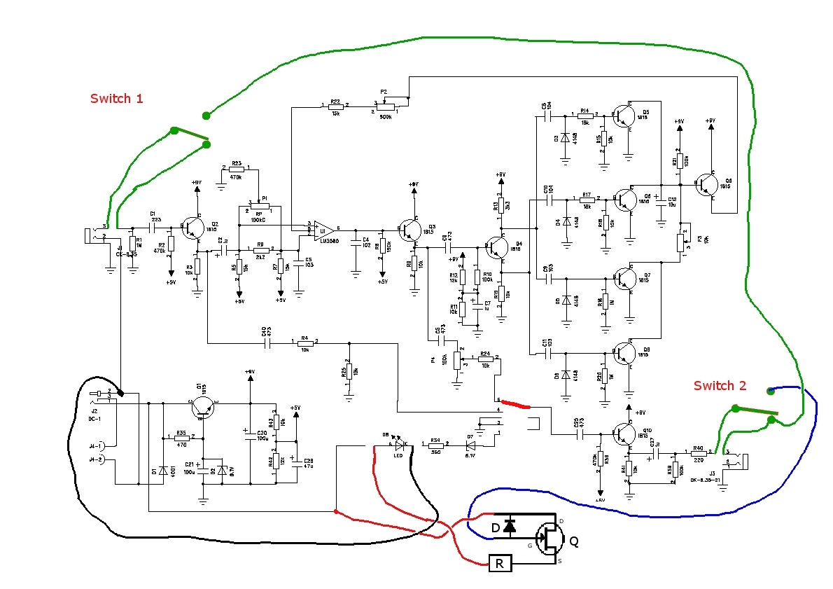
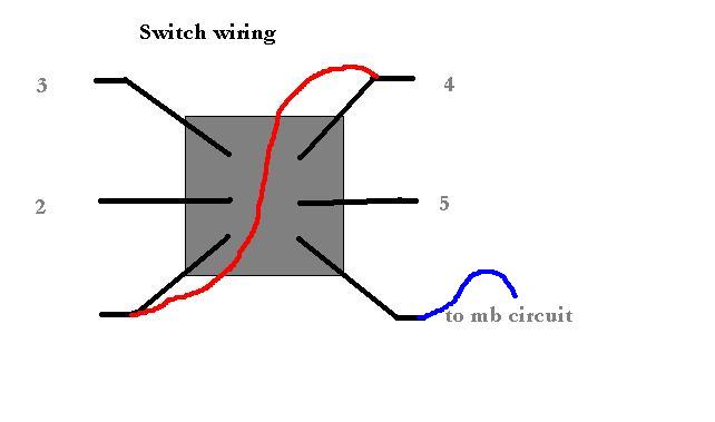
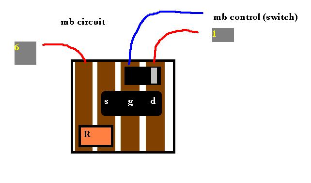
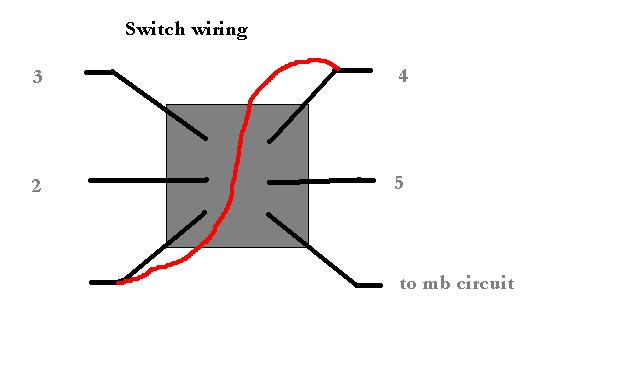
Once again I used the millennium bypass, as I happened to have couple of DPDT switches lying around.

I felt like being super-organized, so I taped all the components to a sheet of paper and wrote down the component values next to them. Maybe a bit excessive work, but I actually got everything right at once this time.

WP_20150923_001

It was the usual routine when soldering, jumpers first, then resistors, polyester caps, electrolytic caps, semicounductors.

WP_20150925_001WP_20150926_001

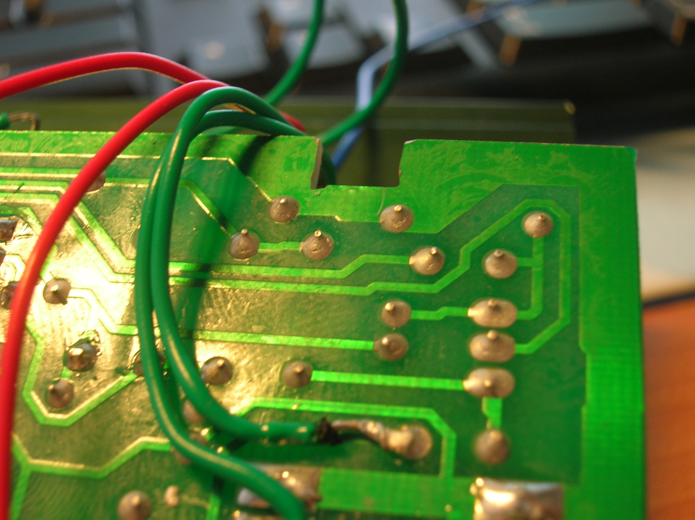
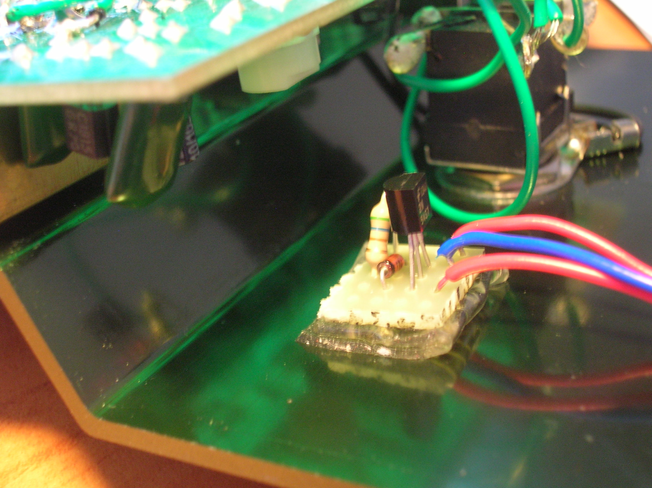
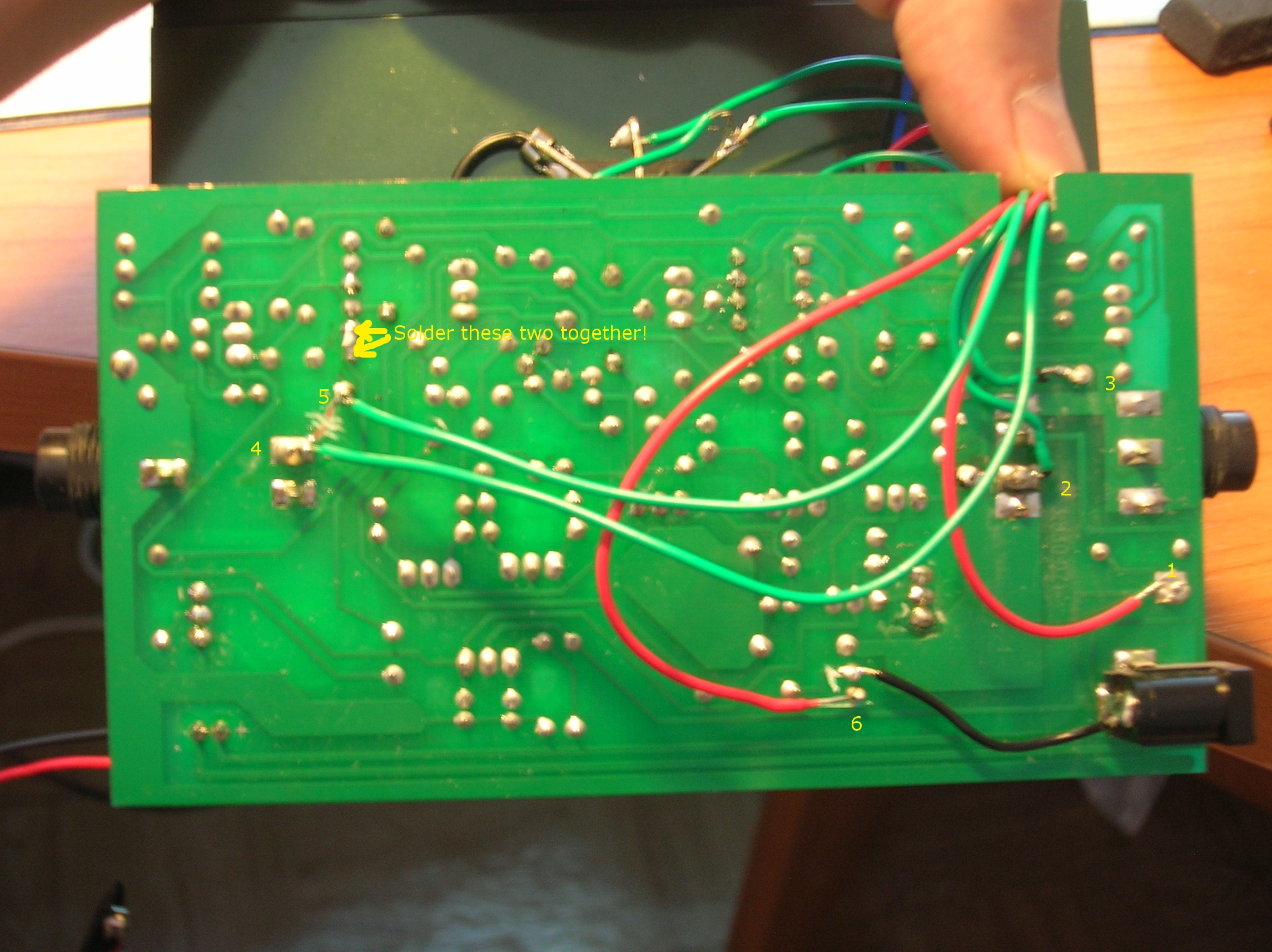
With everything in place I connected the board to all the external parts.

WP_20150926_002

Spot the mistake in the picture above.

I found it the hard way when testing. No sound whatsoever, and my spirits sank. Until I realized I hadn’t put the OTA in it’s socket… Easy fix, and everything worked fine.

WP_20150926_003

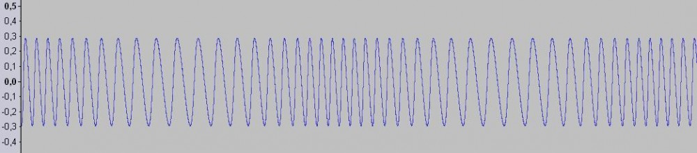
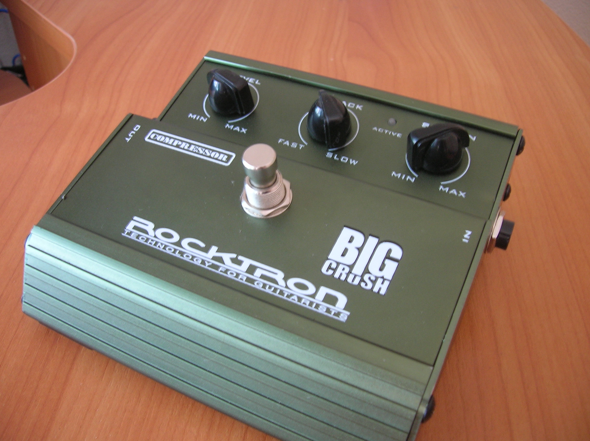
That’s it then folks. I really like the sound, much more prominent compression than my Rocktron Big Crush, more vintage if You like. I could use a little more treble, anyone know which capacitor to change for this? But it’s no big deal, I like the sound, perfect for funk and clean legato lead stuff.

Stay tuned!

Some more bypassing

Hello again! It’s been a while, I’ve been busy with family and stuff. Well mostly family. But the other day I decided to finally convert my CryBaby into true bypass. This is a common mod, and it has been explained in depth many times all over the internet, but I took a slightly different approach to things. The CryBaby (gcb95) basically has two circuits connected in series, a buffer and a filter. The filter part is what makes the wah-wah sound, it’s a resonant filter that amplifies mid frequencies. The rocker on the pedal changes the center frequency of this mid boost. The problem with the filter is that it

  • a: isn’t bypassed properly
  • b. has a very low input impedance

One of these two wouldn’t necessarily be a problem but the two of them combined is trouble. When the pedal is bypassed, the input is still connected and as the input impedance is low, it will load down the guitar signal. This is why the buffer is added to the circuit. The buffer lifts the input impedance to acceptable levels (ca 1 megaohm). However, if the circuit was bypassed properly, the buffer wouldn’t really be needed at all. Here’s how I did it: First of all, I tend to be somewhat reluctant to making too drastic changes to my pedals. By this I mean that want to be able to mod the pedals in such a way that they can easily be returned to their original state. So I wanted to keep the buffer but still have true bypass and be able to play without the buffer when needed. Sounds reasonable, right? What I did was to disconnect the two circuits (buffer and filter). This was the most drastic thing i did to the pedal, as it included cutting traces on the circuit board. I cut the trace between the input of the pedal and the input capacitor of the buffer circuit. The other cut i had to make was between the output of the buffer (at the emitter of the first transistor) and the 68k input resistor of the filter part of the circuit. I also had to add wires to the input and output of the buffer and the filter input at the mentioned points. See picture below. ( sorry for the bad pic) cb1 There was no need to add a wire for the pedal input, as it already existed (the green wire on the ribbon contact). This was really all i had to do to the circuit board, the rest was done around two switches. The original bypass switch is a single pole switch, so this had to be replaced. I happened to have a couple of double-pole switches so it was an easy operation. Here’s a schematic of the switching: cb2 As you can see there are two DPDT switches, the first one (S1 in the schematic) bypasses the buffer, and the second bypasses the filter (this is the switch that is in the place of the original SPDT switch). The first switch is a small one, placed on the left side of the pedal, right next to the output socket. DSCN8658 DSCN8650 The capacitor on the small switch is simply an output capacitor for the buffer circuit. It was easier to solder it directly to the switch. And that’s it! Now I have two bypassable circuits in one. The buffer can be on all the time or bypassed by the flick of a small switch. The filter part can also be used on it’s own. The reason why I wanted it this way is of course mainly to prevent loading on the guitar pickups in bypass mode, but also to be able to use the pedal as an input buffer for the whole pedalboard. The wah now sounds slightly different, not necessarily better (or worse), but the big change is in how the pedals connected after the wah sounds. My fuzz sounds way better now when there’s nothing stealing signal between the guitar and the fuzz. When I don’t feel fuzzy, I can add the buffer and have some more treble to use with other overdrive pedals. There’s one tiny problem still. When the buffer is activated, there’s an audible thump noise when the filter is activated/bypassed. Can probably be fixed by adding a large resistor in a strategical place. I’ll get back to you on that one. Stay tuned (as always!) (and yes, I will continue with the tremolo project soon…) Edit: Corrected some major spelling errors (seriously, in what state did I write the original post?). I added a 1M resistor between buffer output and ground. This drains any build-up voltage on the output capacitor to ground. This solved the click-problem mentioned above. (kind of, there is still a bit of a thump when the filter is turned on and off, but it’s no worse than you would usually expect from a mechanical switch)

Designing an effect pedal, part 1: vision

When I first got into building audio circuits, one of first things I attempted was a tremolo pedal. It didn’t turn out great. In fact, I did manage to put a working piece of electronics together, however it didn’t work out as good as I hoped for, and I decided to redo it from step one.
The tremolo effect. The tremolo effect basically means (periodical) amplitude modulation. It is sometimes confused with vibrato, which is (periodical) frequency modulation. One big reason for this mess might be that fender calls the amplitude modulation effect in their amps vibrato, and the pitch-shifting device on their guitars is called tremolo.
There are several ways to achieve this effect, but usually one would use an lfo (low frequency oscillator), a device that generates a modulating waveform, and have the generated wave modulate the amplitude (volume) of the audio signal that is to be processed. The lfo is a rather simple circuit, usually an amplifier with positive feedback. The interesting part is the modulation itself. It can be achieved with transistors, but I’m going to use optical modulation, or to be more precise, an optical isolator. But more on the tech stuff later, here are the features I want the pedal to have:
– low noise and little coloration of the sound
– an lfo with a wide frequency range
– dual lfo waveforms, triangle and square waves, for both soft pulsating modulation and hard chopping sounds
– controls for adjusting output level and the balance between modulated and original signal
– true bypass, status led, and everything should fit into a standard “mxr box”.
So, that’s what I aim for, I’m going to write a series of blog posts on how the project proceeds. (It’s going to be quite in-depth, so don’t be scared of the more theoretical stuff.)
Stay tuned!

Pedal bypass surgery

A few years ago I bought a Rocktron Big Crush compressor pedal. It’s a nice transparent compressor and it sounded great right away. As long as it was active. When in bypass mode, it was the worst pedal ever. It had buffered bypass, which isn’t necessarily a bad thing, but in this case it was terrible. There was a big volume drop and a major loss of bass frequencies. So I’ve thought about turning it into true bypass for a while, and now i finally had the time (and courage) to do it.

DSCN8620

Why true bypass? True bypass means that the circuit is mechanically removed from the input and output when the pedal isn’t active. This is usually done with a DPDT-swich (two on-on swiches in one package), but because most pedals have a led that lights up when pedal is activated, there’s need for either a third switch (which calls for a 3PDT-swich) or one of the existing switches has to be used for this. Another solution is the millennium bypass, of which I already wrote in the fuzz-post. When the signal path is completely removed from the circuit in bypass mode, there’s no extra load on the signal, and therefore no loss of any frequencies, which might be the case when using (bad) buffered bypass.

So the pedal already had a DPDT-swich, which isn’t always the case in buffered bypass pedals (most of them use FET-switching). What I had to do was to disconnect the inputs and outputs from the rest of the circuit, and because I intended to use millennium bypass, I also disconnected the led. This was done by simply cutting off the copper trace on the circuit board in the right places (red lines).

DSCN8608

I then soldered wires to the right places to the underside of the board, green wires for bypass and red for current to the led.

DSCN8619

Because of the way the cicuit board is held in place inside the pedal, I had to cut a small “bay” in the side of the board so the wires could pass through.

DSCN8615

The led switching circuit was placed right next to the switch using double sided mounting tape. The circuit is roughly the same as in the fuzz, it uses a different diode and a smaller resistor, but the principle of operation is exactly the same.

DSCN8613

I found the schematics online (bad resolution, but it’s readable), here’s what it looks like after the modification:

BigCrush-2

(Note that R24 needs to be connected to C25. The easiest way to do this is to solder pins 5 and 6 on the ribbon cable base togehter). The parts used in the bypass circuit are: Q = 2n5457 FET, R = 560 ohm resistor, D = 1N1418 silicon diode.

One thing that I noticed is that when there is no plug in the input of the pedal, the led stays on all the time (if the power cord is connected). First I thought I had done something wrong, but this i simply because the ‘ground’ of the whole cicuit isn’t really grounded until there’s a plug in the input, a design meant to save batteries. This is not a big deal, because I never run my pedals on batteries. Apart from this, it works totally fine. Now as the pedals major flaw has been corrected, it’s a really good compressor, and will find its way back to my pedalboard!

EDIT: By request, I added three more pics with more detailed information on which wire goes where (see numbers) and a stripboard layout for the fet switching circuit. I hope this will be helpful!

dscn8619

sw

mb

N.B. the pin order on the fet might differ depending on the fet used. Check the datasheet.

Let’s go fuzzy!

So the treble booster is running fine, but the promised demo is still on the to-do-list. But while waiting for that one, let’s take a look at the next project. It’s time to add some fuzziness to this blog.

I once again went for a circuit I found online, this one, to be more precise. It’s basically a traditional fuzz face style circuit, only with some minor changes in components and some extra features. I had to adjust some component values according to what parts I was able to find. Here’s my version of the circuit and the parts used:

fuzzschema

The pedal will have controls for attack, smoothness and output volume, with an internal trimpot setting the bias for the second gain stage. It will be housed in a standard aluminum box, and there will be a status led lighting up when the pedal is on. This little led however, combined with the fact that I only had a 2-pole switch (DPDT) available, means I would have to sacrifice the true-bypass feature, or I can use the Millennium Bypass (MB). The MB is a really clever little circuit that allows for true hardware bypass and a status led using a 2-pole switch. It uses FET-switching for the led by taking the leakage current from a diode to “open” the FET which feeds current to the led. I used the Millennium 1 version with some modifications, and it works just fine. The geofex website from where this circuit is taken states that there will be a tiny turn-on time for the led, but I didn’t notice any of this using a ultra bright blue led. I also had to add a 1M resistor after the volume pot to prevent the led from lighting up randomly in off-mode. This will ground the gate of the FET and make sure that the led stays off. For practical reasons the switching curcuit is on a separate board, and the current limiting resistor is soldered directly to the led. The bypass curcuit then looks something like this: (the m.b. lead on the circuit pic connects to the Cont lead on this pic)

mb

I painted the box in a nice green color using Revell email paint (the paint used for model planes).

P1080377

Once again I used stripboard for the curcuit board, and with some careful planning I managed to fit the board above the pots inside the case. Here’s everything in place inside the box.

fuzzin

And finally, the finished pedal:

fuzzut

(The last picture was taken using a different camera, so the color became a little pale, the first picture is more accurate)

So, how does it sound? Well, it’s no hi-gain pedal, but it has a nice smooth fuzz. The bottom left knob controls the pre-gain. Turning this down clears up the distortion much in the same way as turning down the volume on the guitar does. Bottom right is output volume, and upper right is “attack”, which essentially is a tone control. The one thing I really couldn’t find was a inverse logaritmic potentiometer for this one, and it really has its usable range between 2 and 5 o’clock. Might fix this in the future, but it’s not very high on the to-do-list.

Stay tuned for the video demo!

Edit: updated the “attack” (tone) control to an antilog potentiometer. It was a little hard to come by, but totally worth it. Now the attack control is usable in its entire range. Now I’m thinking about changing capacitors for higher quality stuff. But we’ll see about that…

A first attempt at distorting signals

A while ago I started building a treble booster, pretty much based on this circuit. I had actually completed the build when it turned out there was something wrong with the circuit (hence the name of the blog). The project was put away for some time, but then a few weeks ago I decided to give it a new try and not to give up until i had a working pedal. Boost the signal or die trying.

The circuit itself is pretty simple. Basically it’s just an (intentionally) badly designed amplifying stage. The signal gets amplified in a quite non-linear way as the cicruit will indeed boost the higher mids and treble, but it will also add quite a bit of overdrive. Here’s my version of the circuit:

boostschema

R3 should actually be placed after the Rx resistor, this allows the bypassing of Rx to affect the biasing of the transistor, as R2, Rx and R3 form a voltage divider.

The parts used are: BC107B transistor, R1 = 1MΩ, R2 = 120kΩ, R3 = 39kΩ, R4 = 10kΩ trimpot, R5 = 2,2kΩ, R6 = 390 kΩ, R7 = 10kΩ potentiometer, R8 = 100Ω and R9 = 220Ω. C1 = 22 nF, C2 = 68 nF, C3 = 10 μF electrolytic and C4 = 100μF electrolytic. D1 = 1n4004 and D2 is a red led.

The Rx resistor is bypassed by a SPDT switch and the whole cicuit uses a 3PDT switch for bypass which means it’s true bypass.

I decided to use the BC107 transistor as it is a fairly good compromise between a sound some people might call “vintage” and features that makes it easy to use in a practical situation (i.e. NPN which makes it possible to use negative ground and thereby a shared power supply, and it’s silicon which makes it a lot more resistant to temperature changes, or at least that’s what the internet says, haven’t actually used germanium transistors).

I built the circuit on stripboard which is an easy way to get a lot of parts fitted on a small surface without having to mess around with any etching chemicals. Here’s the stripboard layout:

boostlayout

After some trial-and-error I finally got it put together, here’e what it looks like now, inside and outside:

inpedalutpedal

I decided to give it a rather fancy look, by using a aluminum knob for the voulme control and sanding the surface with a quite rough sanding paper. The design was inspired by my old hi-fi reciever, I found this suitable as the treble booster might the most lo-fi circuit ever used for guitar processing.

I will post a video demo soon, I just have to find a place where I can play it loud enough to make the booster justice. Can’t really do that in my appartment.